Total Pageviews

Monday, September 16, 2013

New Closed Valve Symbol in P&ID

The scenario was we needed a Normally Closed Diaphragm valve symbol and it was not there.
 
Here is the procedure to add it.
 
Go to the Project's PROJSYMBOLSTYLE.DWG and insert the "open" valve symbol.
 
Explode the symbol and block it to the new name... in our case it was PIP DIAPHRAGM VALVE (CLOSED)
 
Open the new block in Block Editor and hatch using Solid to fill in.
 
 
Delete the block from the view (do NOT purge) and save and close the PROJSYMBOLSTYLE.DWG
 
Open Project Setup of the current project and ADD a new symbol to the Diaphragm Valve
 
 
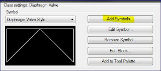
Create the NEW name of the Symbol... again in our case it was DIAPHRAGM VALVE CLOSED STYLE.  You'll see it below but do not set that as your default symbol.
 
 
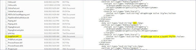
Lastly, go to the PnIDPart.XML and edit the file to have it place the CLOSED valve instead of the OPEN valve.  See below.  I use Notepad ++ to edit XML files.
 
 
Close out Plant 3D /P&ID and reopen to see changes take effect.

AU 2013 Registration has opened up!


Sign up for the PLANT 3D classes (CLICK HERE!)
 
Including my class "PD2297 - Autodesk® AutoCAD® Plant 3D: Tricks of the Trade" on Wednesday at 2:30PM!
 
In this class, we share some of the tricks we have learned over the years for working with AutoCAD® Plant 3D software. We cover various ways to route pipe, including rolled offsets, L2P, sloped, “F” as you go, elevations, and compass settings. We teach you to create equipment templates and use Viewports in Plant 3D modeling. We cover X-ray view, layer and template options, and iso messages and breaks. We explain the model symbols, such as triangles, pluses, inverted triangles, arrows, and the red line of connectivity. Finally, we cover the proper method of making line and inline asset size changes.
 
See you in Vegas!